I purchased 2 thermoelectric chips with hot and cold heat sinks. Testing them I found they pull 4 amps at 11.75 volts, so about 50 watts each.
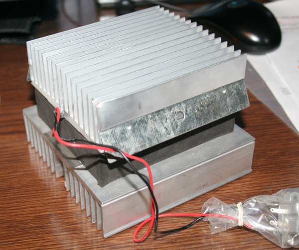
ThermoElectric Device: LWKW Thermoelectric Heater Cooler Peltier
Junction
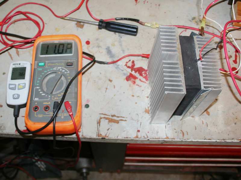
LWKW-0318Ampmeter & Voltmeter Closeup: Test current draw going into the LWKW-0318 thermoelectric cooler.Ampmeter & Voltmeter Closeup: Test current draw going into the LWKW-0318 thermoelectric cooler.
Thermoelectric Heater Cooler Peltier Junction LWKW-0318
Ampmeter & Voltmeter: Ampmeter and Voltmeter testing the ThermoElectric device.
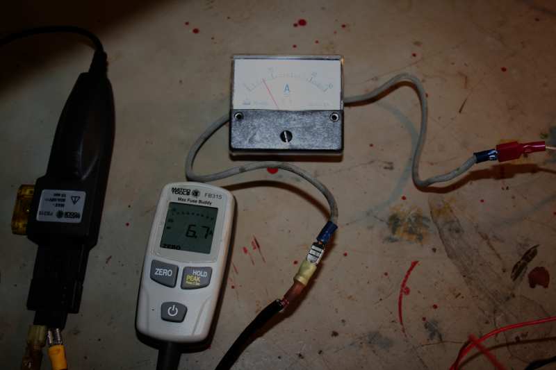
Ampmeters both Digital & Analog: Testing the Thermoelectric device
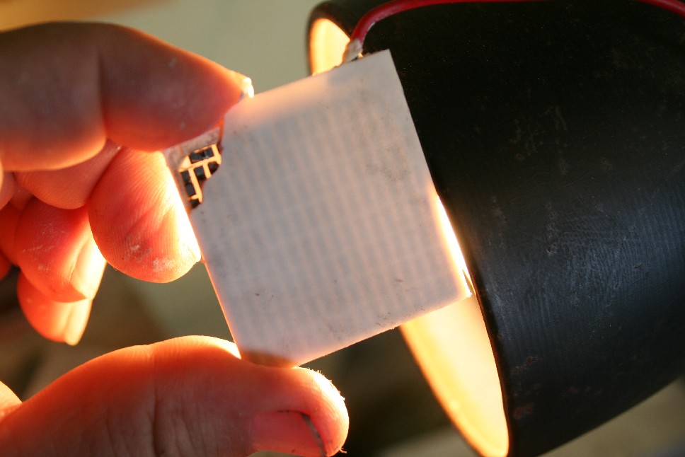
Hot Side: Hot Side Thermoelectric Heater Cooler Peltier Junction LWKW-0318

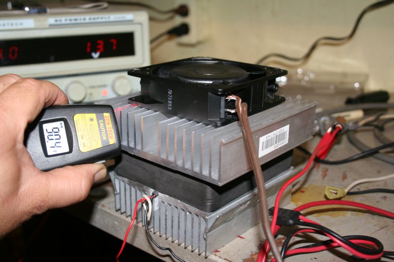
ThermoElectric Device With Cooling Fan Hot Side:
Cold Side: Cold Side Thermoelectric Heater Cooler Peltier Junction LWKW-0318

ThermoElectric Device With Cooling Fan Hot Side:
With a air cooled heat exchanger working on the hot side removing the heat. The non-contact thermo-sensor shows 90°F OK to touch. Without the fan the aluminum was very hot to touch. When the fan was first turned on, after the TEC was run for 10 minutes, obvious hot air was flowing out. I have ordered a better temperature sensor using contact probes.
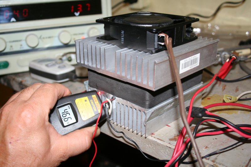
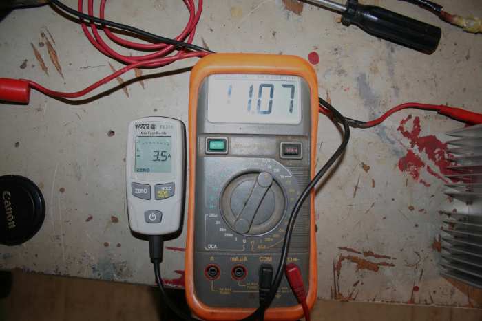
: Cold side after running the cooling fan for a few minutes.
Temperature drops to 46°F. Moisture building up on the fins. A larger unit would require water collection like other forms of cooling do.
[[http://saturn.lynnautorepair.com/ThermoElectric%20Air%20Conditioning%20%2526%20Options%20For%20Electric%20Vehicle|Some Background on EV Air Conditioning here.]]
The hot side showed 137°F on the aluminum heat exchanger. The room temperature is around 91°F. The low side gets cool for a minute then raises to around room temperature. When the hot side heat is removed in a bucket of water the low side will drop to 59°F.
So the trick is the hot side must have the heat removed in order to have cold air when blown across the cold side. Maybe if I expose the hot side to outside airflow and add a small cooling fan the heat exchanger remover can be, by air cooled and not have to have to be water cooled with a transfer pump etc. I do have the pump and other parts left over from the [[http://saturn.lynnautorepair.com/node/189|old liquid heater system that was removed]] when I [[http://saturn.lynnautorepair.com/EV%20Hot%20Liquid%20Heater%20to%20a%20Ceramic%20Heater|changed over to a ceramic heater.]] Another option is to use the thermoelectric cooler to also heat the air by reversing the leads manually or by a switching device.
The TEC devices could be placed where the old evaporator core once was. I removed it the last time I had the HVAC housing out to do the ceramic heater. However the TEC devices are placed the hot side must have the heat removed or we get no cooling on the cold side.
I have purchased 3 other TECs. One has arrived and the other 2 are on the way. I am trying to come up with a setup that produces alot of heat transfer within a small space that I have under the dash.
When checking the resistance of the different chips I realized I was getting wrong and changing readings. Because of the Seebeck Effect (then the two sides are different temperature the TEC puts out current, so a standard ohmmeter will not work. A standard ohmmeter uses a few millivolts on one side and see how much returns on the other. With a TEC voltage is being produced. -Can you test a TE module with an ohmmeter? No – the DC voltage that a standard ohmmeter applies will cause a temperature change (Peltier Effect) which will in turn cause a voltage to be generated (Seebeck Effect) which will cause the ohmmeter to read strangely (drifting, and even a ‘negative’ resistance. So, then use the “diode test” position on the ohmmeter? No – even though a TE module is constructed of an array of N and P doped semiconductors there isn’t an actual diode junction. A resistance test can be made with an LCR meter which measures resistance using an AC voltage. Using a HP 4274A LCR meter expect to measure a few ohms for small modules and a fraction of an ohm for larger ones. While one does not usually see the resistance parameter specified on manufacturer’s data sheets it is probably not a bad of a check of a module’s health, especially if more sophisticated test methods are not available.