On August 6 the Elcon PFC 5000 Battery Charger quit charging. I brought in the QuickCharger SCPX 220 which is my backup. It
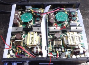
The arrows show 4 possible fuses. The one that was blown was the lower left one by the DC output wires.
is not (in my opinion) as reliable in keeping a even top voltage full charge. I contacted some people who have run Elcons and they experienced a $800 and up repair, and shipping costs sending it to California and back. So I put off the repair until lately.
I emailed Elcon
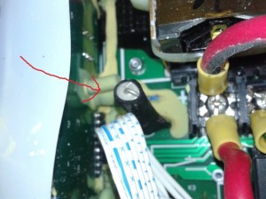
This is the bad fuse before any repairs are done.
describing the symptoms. No charging output, the dual cooling fans come on and the indicator LEDs are flashing Red-Green-Red-Green etc at One second intervals. The definition of that code is battery disconnected. Well the voltage was tested on both sides of the Anderson Connector and conclusion was a good connection.
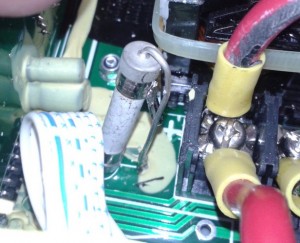
Elcon Internal Fuse with the factory shrink-wrap removed.
I contacted Sayyed A. Bashir at ELCON / Electric Conversions 515 N. 10th Street, Sacramento, CA 95811. His reply was. Red green LED could mean that the DC output fuse inside the charger is blown. You can check the continuity between the thin yellow-green wire (mine was just green) (bundled with the DC output wires) and the red DC output wire. If there is no continuity, the fuse is blown. You can send it to my attention at the address below with a copy of this email in the box. Cost will be $60 plus shipping back to you.
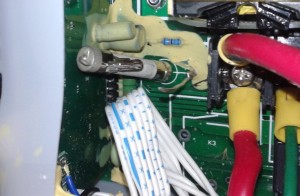
DC Fuse with lead cut.
The charger was ohmed between the small green output and the large red output. There was no continuity, an open circuit. I emailed Sayyed again explaining the warranty was out and I would like to repair it replace this fuse myself and in fact I already had opened up the case. Could he work me through it? He graciously replied…
You can confirm that the DC output fuse is open by removing the cover and checking the continuity between the terminal where the thick red DC output wire comes out and the terminal next to it (with the thin green wire).
The DC output fuse is in the corner near the DC output terminal block. It may be a white cylindrical pigtail fuse vertically mounted with black heat shrink tubing around it or it may be a orange or red automotive fuse. Replace it with exactly the same kind of fuse. It is soldered to the main circuit board. Since it is not easy to replace this fuse, we recommend that you allow us to replace it.
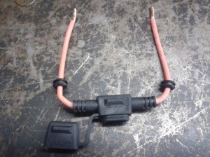
Fuse Holder with grommets
So I located the fuse removed the shrink tubing and tested finding an open fuse. So I here document the replacement of that fuse.
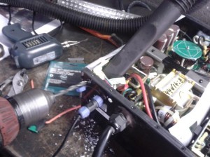
Drilling Elcon PFC 5000 to install the external fuse to replace the blown internal fuse
The original fuse was like the old automotive AGA glass fuses except this fuse had a ceramic center body around the element.
For now to see if the charger will work and to keep from disassembling the whole thing if another fuse blows in a month I need something different.
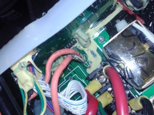
Soldier the external fuse wires to the original connection points.
An external fuse and fuse holder. An ATO blade fuse and holder was the most available. Drill 2 holes in the aluminum case and install grommets run the wires through then attach to the old contacts.
Next was to soldier the wires to the original points in the charger.
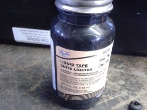
Liquid Tape, handy item, good insulator
A good way to insulate odd shape conductors is Liquid Tape which was used on the exposed wires.
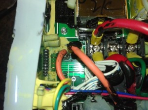
Here the fuse holder wires are insulated with the Liquid Tape.
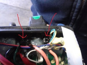
Here the 2 wires go through the aluminum case and grommets and 2 plastic ties are installed to stabilize the internal wiring if the holder is moved.
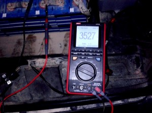
Checking voltage on one cell to see if charger is working now. Looks good so far.
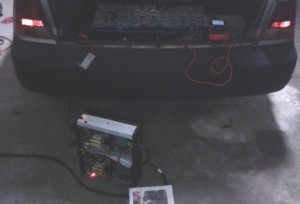
Trying out the Elcon 5000 with the repaired now external fuse.


