Testing a thermoelectric air conditioning system. Will try some things, see if it is practical enough to install in the EV Saturn.
12 Peltier Chips Arranged: Arranging the chips different ways to get 12 on the available heat sink surface.Fiberglass Frame: Fiberglass Frame that will hold the Thermoelectric Machine and bolt to the EV
First Stage Plans are:
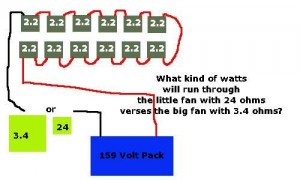
This machine will have 12, 90 watt 12706 Peltier modules. Running 160 volt DC off the Saturn EVs battery pack will create a watt power of 960 watts at 6 amps. I am considering including the big hot side cooling fan in-series to drop the amps to below 6. Six amps is the max recommended for a 12706 chip.
I had troubles with Peltier modules I ordered on eBay. I tested all 10 chips purchased from one eBay seller. 6 volts and later 12 volts were run through them and measurements of the cold side, hot side and amp draw of each at different times like 30 seconds, 1 minute etc. Out of 10, 6 were defective and later I will find one is wired backwards. All chips when laying flat with the wires towards you and the red wire to your right; the cold side will always be up. Well after assembling the pack and running it on the table I noticed one side was not as cold. Disassemble, and found one chip was putting hot out on it’s cold side. Flipping the chip I found it’s hot side was cold. So I flipped it over and continued.
Next problem, the heat sink compound was not uniform. Parts were watery and parts of the tube were dry and hard to spread. I probably put too much on the chips but I was basing it on how much the other chips had on them when purchasing and disassembling.
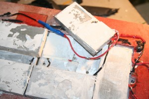
Removal of Heat Sinks Because Chip was Wired Backwards: When looking at a Peltier module if you put the 2 wires towards you and the red wire to your right the cold side is always to your right. Well except with this one module was wired backwards.
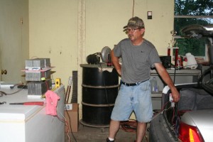
Testing with Battery Pack: Testing the thermoElectric machine without fans. Connected to the EV Saturn’s battery pack
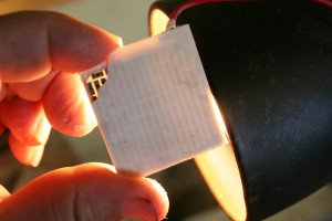
Peltier chip innerds: Each ship has 127 pairs of Bismuth Telluride pairs. The pairs of P/N pellets are configured so that they are connected electrically in series, but thermally in parallel. Metalized ceramic substrates provide the platform for the pellets and the small conductive tabs that connect them. The pellets, tabs and substrates thus form a layered configuration. Module size is 40 mm x 40 mm.
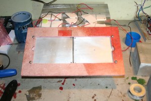
I cut out a piece of fiberglass to bolt to the center of the thermal machine and later bolt the fiberglass to the vehicle firewall.
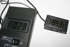
Next step, wire Thermoelectric module to the EV 159 volt battery pack. The following chart shows the results with a 220 CFM fan on the hot side and a 35 CFM fan on the cold side. The ‘cold air’ and ‘hot air’ columns were tested with a handheld non contact infrared temperature sensor.
| Centigrade | 159 volts | 220CFM | 35 CFM | ||
| Hot Side | Cold Side | Amps | Time | Hot Air | Cold Air |
| 28 | 28 | 0 | Before | 28 | 28 |
| 28 | 28 | 6.6 | 5 seconds | 28 | 28 |
| 32 | 24 | 6 | 1 m | ? | ? |
| 43 | 20 | 5.6 | 2 m | 37 | 25 |
| 48 | 18 | 5.3 | 4 | 43 | 22 |
| 51 | 17 | 5.2 | 8 | 42 | 21 |
| 51.9 | 17 | 5.2 | 12 | 49 | 20 |
| 52.1 | 17 | 5.1 | 15 | 48 | 20 |
The same tests were run again with the larger blower in series with the Peltier Module 12 chips. The main change was the amperage dropped 8% and the temperature difference was slightly less.
The fan measured 13.9 voltage drop across its positive, negative while in-series.
Tested the system with water spray added to the hot side blower-cooler without any measurable difference in temperature.
Disassemble module to check chips again because output is disappointing, see if any chips have failed, maybe much compound is causing a heat transfer problem and check for condensation water between hot and cold heat-sinks. Upon dis-assembly one chip broke because o when the two sides were pulled apart they were very stuck together and a rubber hammer was necessary when some chips stuck. Used a razor blade to remove heavy thermal compound. Clean chips further with rubbing alcohol and coffee filters. There were some water droplets between the sinks.
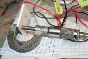
Decided to measure the thickness of the chips and found a large difference in some. Eight of the chips were .131″. three were .148″ and one was .154″. so I ordered some more chips from another eBay seller.
Micrometer measuring the thickness of all the TEC 12706 chips. This one measured .135″
Two issues now, as I see it.
One hot side too hot, need to remove more of it’s heat so to get the cold side lower. Two, amperage is s little too high. Would like about 4 amps.
New chips arrive. I test them for amp draw at 12 volts, make sure they work, not wired backwards and are of uniform thickness.
Tests are good. All measure from .132″ to .136″ thick. Most were .134″ to .135″. The largest and smallest were not used. New chips are 12706 just like the older ones already tested but these seem to have a larger resistance since they register 1.9 to 2.0 amps at 7 volts. That would be a resistance of 35 ohms.
The option of bolting the chips between larger heat sinks means drilling holes in them. Bolts should be in the center of the sinks but they have fins that cannot be removed and there is no room for the bolts other wise. So, decide to stick with the original plans with the slightly smaller sinks. reassemble with less compound this time. Try several ways with the larger heat sinks bolted to the smaller sinks moved away and inch and bolted up and without the extra sinks.
Run and test the new 12 chip TEC machine and fan with the 159 volt battery pack on the Saturn. Each of the 12 chips had a voltage drop of 11.9 volts and the hot side fan (was installed in-series) had a voltage drop of 11 volt.
The amp draw was 3.5 amps at start-up and slowly dropped to 3.44 amps after 17 minutes with a high side of 45°C and low side of 25°C. Note the Infrared temperature sensor showed hot side of 45°C to 60°C and low side of 25°C to 29°C.
The same tests were run with the 12 chip TEC without the fan in-series. Amperage rose to 4 amps.
Disassemble pack again because one side shows hotter then the other on the cold half.
Found this cracked chip with a black burnt crack after using for only 20 minutes.. What’s happened? I may have dropped that chip right before installing when I removed it from its bag. Only fell a foot or so.
After assembling pack (seems like 9th time) I run the 159 volt tests. They were about the same as the chart above except that the amperage has been lower since the new chips were added.
Conclusion: So far is the machine will not cool the electric vehicle enough to be comfortable during the hottest days of summer. Maybe on 90°F and below days. I must decide whether to install the machine in the dash or not.
BTW
The EV batteries were tested while the thermoelectric device was pulling about 4 amps (for 25 minutes)and all 48 batteries showed 3.23 volts. Very uniform.
VIDEO of ThermoElectric Testing
