First let me say that the following discussion is what I have tried to do to make the original tachometer work in the SS Saturn EV. Up to this point it still does not work.
But as Thomas Edison said “I have not failed. I’ve just found 10,000 ways that won’t work. ”
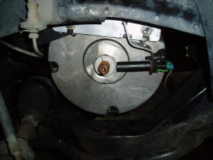
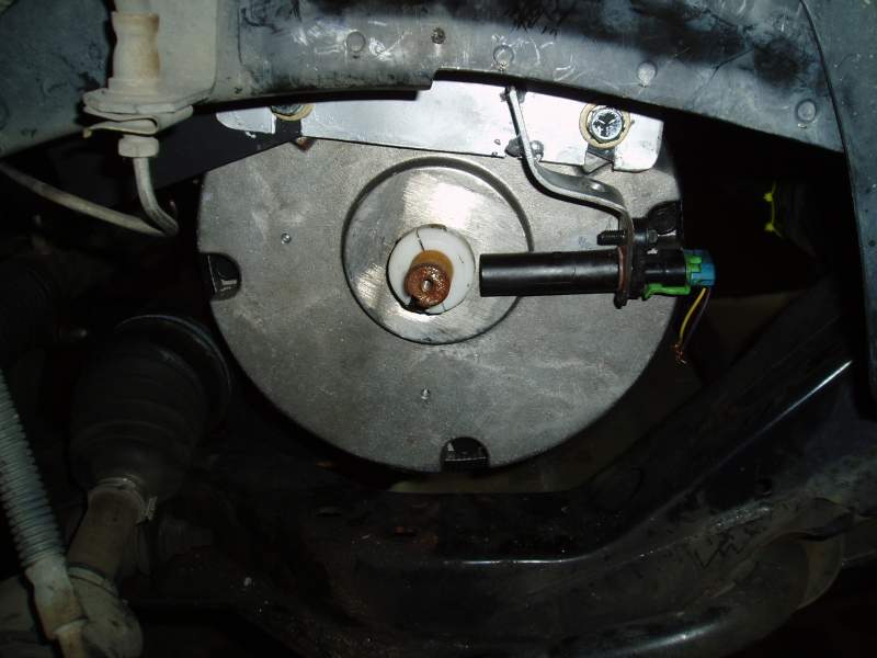
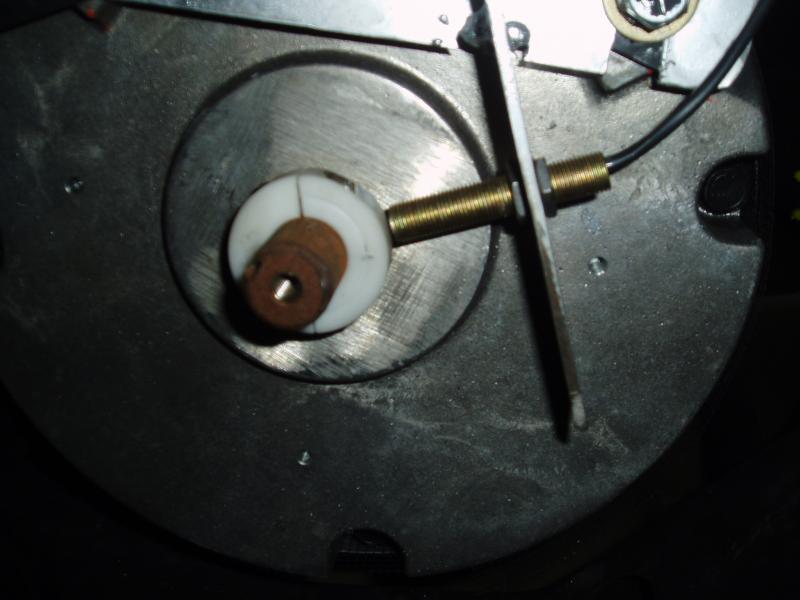
- Original Crank Sensor Installed on electric motor
-
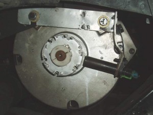
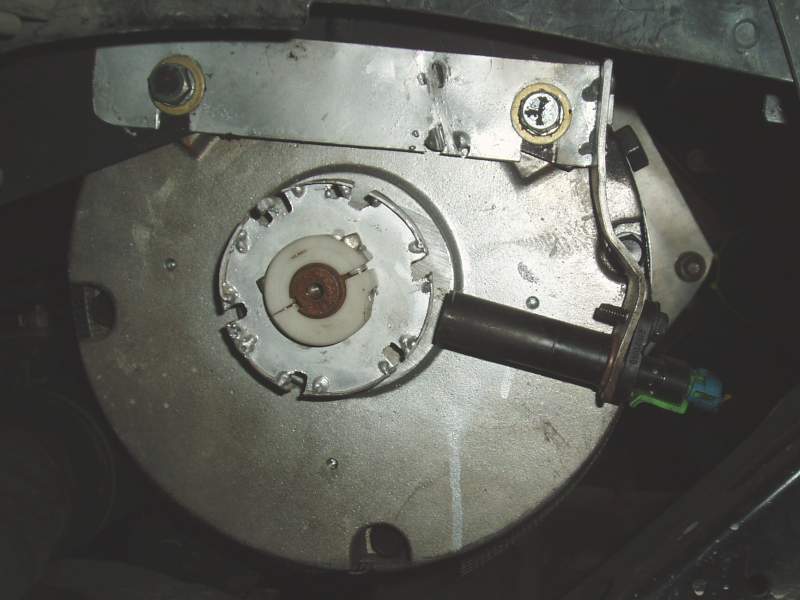
- new reluctor ring attempt
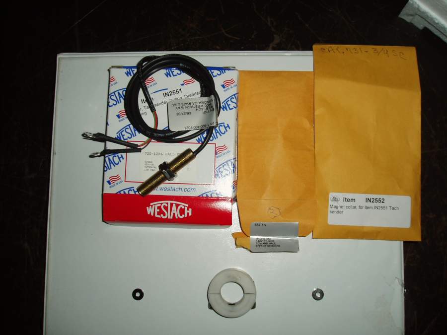
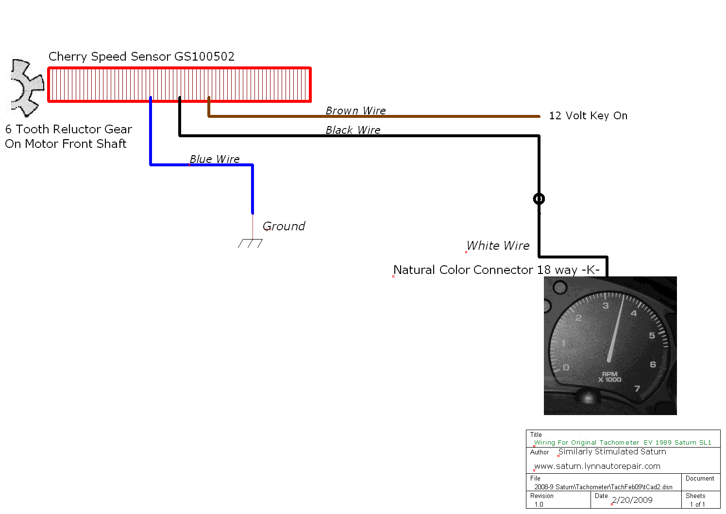
Cherry Sensor
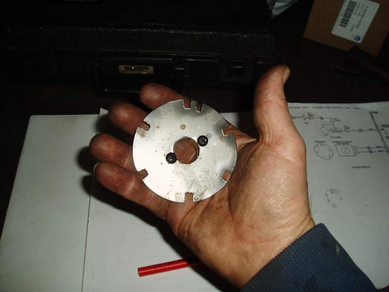
tach speed sensor and ring
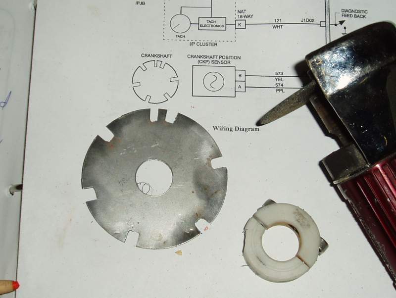
wide and narrow notches
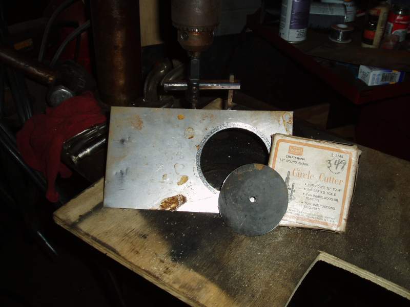
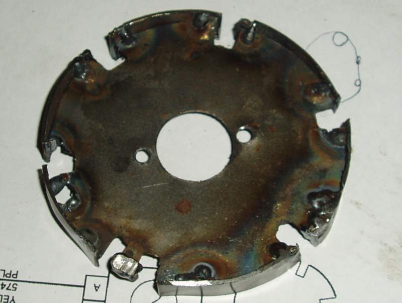
Cutting out reluctor ring from sheet metal
Coil Firing from signal given
cutting notches
Next
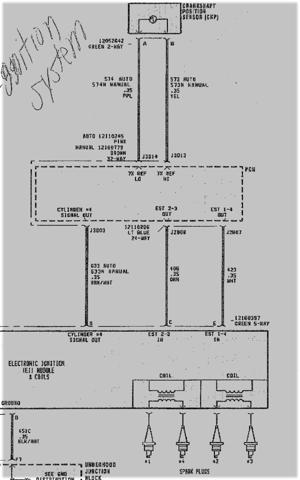
I removed the original cranksensor form the Saturn engine out back (never throw away any removed conversion parts for a least a year). I looked in the hole in the block where the sensor rode and noted the crankshaft ring did have 7 notches, two were close to each other and the others were evenly spaced. In the wiring diagrams I included, there is a drawing of the reluctor. The 5/16″ thick ring was probably 6″ in diameter.
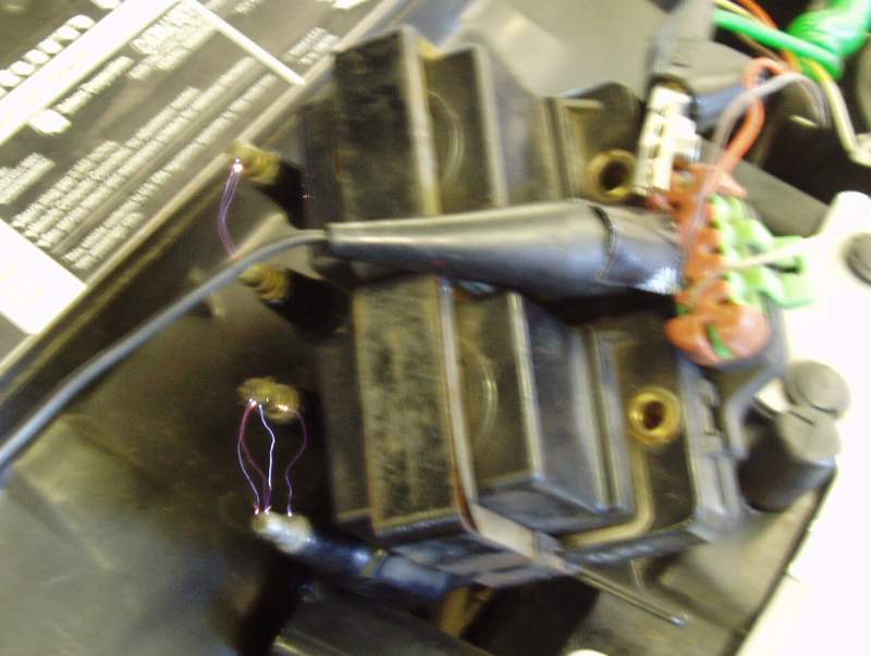
I installed this sensor where the store bought sensor had been and I used the same magnet ring. I wired up the original crank sensor wire Yellow reference high and Purple reference low. See the wiring images below.
For the first time my graphing voltmeter (weak scope) showed a nice pattern up to 3 volts when the motor was revved up. Still no movement at the tachometer.
Next I connected a GM TECH 2 scan tool and looked at data off the PCM while reeving the motor. I did get a RPM reading but it was sperratic.
I cut the white wire that goes from the PCM to the tachometer and grounded the tach wire several times. Once and a while the tach needle will move.
Next Plans
Make a reluctor ring like the original one that is made on the crankshaft. This one will be about 3″ in diameter instead of the 5 to 7 inch one.
The first ring I cut out of 1/32 steel with a Sears circle cutter (probably made for wood). Then drilled the center to .750″ to fit the motor shaft. I laid out the ring next to a picture of the original ring, marked then cut out the notches. Then screw it to the plastic ring I had been using. After installing this ring although I still had no tach movement I noticed the fuel pump relay was working. If I disconnected the crank sensor the fuel pump relay would not come on.
The fuel pump relay would click to a rhythm depending on how fast the motor was turning from one click every two seconds to 5 clicks a second when revved to 200 RPM. When I scoped the Green and White wire that runs from the fuel pump relay to the PCM the 12 signal is interrupted for only a millisecond then 12 volts for a full second etc.
I decided to make a Second Ring and have the 7 notches thinner be to more like the original ring in relationship. No better results, in fact you can see by the comparison the first ring created more voltage.
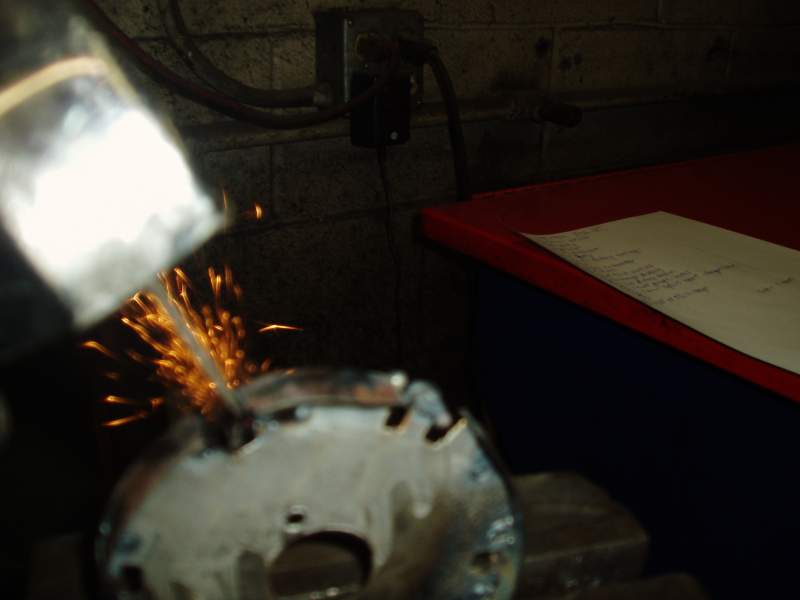
Next idea was maybe the ring is too thin. So I welded a 5/16″ wide strip of steel to the outer ridge of the ring and them notched out all 7. This created the most voltage putting out over 12 volts.
Trying to figure out what is wrong I connected the original coil packs and ignition module. When ever the motor spun over the crank sensor sent the signal to the PCM and it signaled the IG module which fired the coil packs without missing a beat. Bam- Bam the spark alternating form one coil to the other as the motor coasted to a stop. So everything seems to be here. Crank sensor to PCM to fuel pump relay and ignition but not Tachometer.
Maybe the tach has failed, maybe I ruined it during testing or cluster work.
Interesting to note the white wire that runs from the PCM to the tachometer has 12 volts in it coming from the tach. This 12 volts I assume needs to be sine or square waved on and off to move the tach needle.
I even tried to wire this white wire from the tach to the grounding side of the IG module after removing the coils and using the grounding terminal coming out of the module. The scope showed a 12 volt on and off signal but not a tach response.
Cam Sensor: In trying to figure what the PCM is thinking what it is looking for, I studied the cam sensor circuit. You know this original 1998 SL1 Saturn has no cam sensor; but will throw cam sensor codes? p0336 CAM SENSOR CODE.
Here is how both the cam and crank sensor works.
The Electronic Ignition Module does not receive a signal from the crankshaft position sensor. Instead the Crank sensor signal is being received and processed by the PCM. The PCM sends two 5 volt to 0 volt EST signals to the EI module. The orange wire is a for 2-3 cylinders and the White wire for 1-4 cylinders. The third Brown/Whirt wire is the mysterious Cam Sensor signal. The EI does contain circuitry to determine camshaft position without using a camshaft sensor, by use of compression sense ignition or CSI. The CSI circuitry makes use of the characteristics of a waste spark ignition system, while monitoring a sequence of spark plug gap breakdown events. Capacitive pickup plates located under the 1/4 coil are used to determine whether #1 or #4 fired on a compression stroke. A Compression stroke will always require a higher voltage reached before a spark occurs verses a waste spark.(except on decel?) This capacitive sensing device is similar to inductive pickups used on engine analyzers and oscilloSCOPES. The EIM grounds this cam wire every time it see #4 compression which should be every 14th crankshaft event or signal.
So does the PCM require a cam sensor signal to run the tachometer? It will never get one because the EI module cannot see compression stroke on #4 cylinder because on a EV conversion there is no compression stroke, #4 cylinder etc. How could I fake that?
Or maybe the reluctor ring I made is not accurate enough?
Summarize:
Got a good rpm signal off the front motor shaft that the PCM accepted enough to signal the fuel pump relay on and to fire both coils without any noticeable skips from about 2500 rpm to less than 100 (see picture). No tach movement.
O well..
So the latest is, over 8 hours this weekend were put strateging and fabricating without success. But this might be information someone could use or someone might comment here and give me an idea. Otherwise I will put tachometer plans on hold for now.
At least got the Quick Charger repaired and returned, and the Saturn back on the road this week.