The Liquid type heater I used verses a ceramic heater was an involved deal. I purchased the components from www.EVAmerica.com at a cost of $500. It was made by Classic Electrics http://www.classicelectrics.com .
The components include the: heater box, pump, coolant reservoir, contactor, Anderson SB-50 disconnect, fuses, relays and some mounting hardware and hoses and clamps. The hoses and hardware were cheap but the rest of the kit was quality stuff.
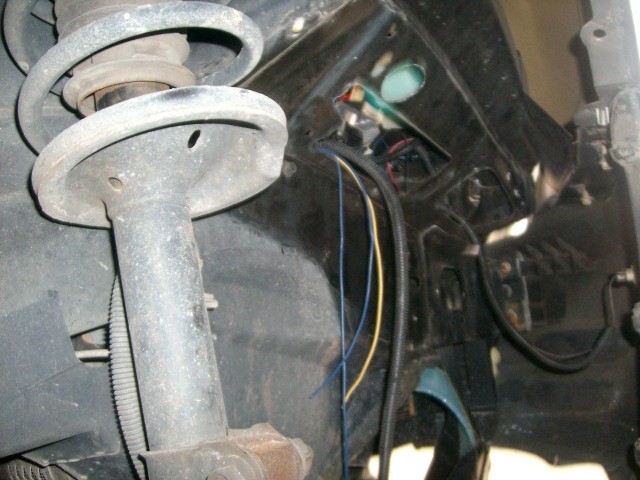
Heater Box Area in Right inner fender in front of tire
I installed the heater box inside the right inner fender behind the bumper.
This was done similar to the power brake components that are in the left inner fender area.
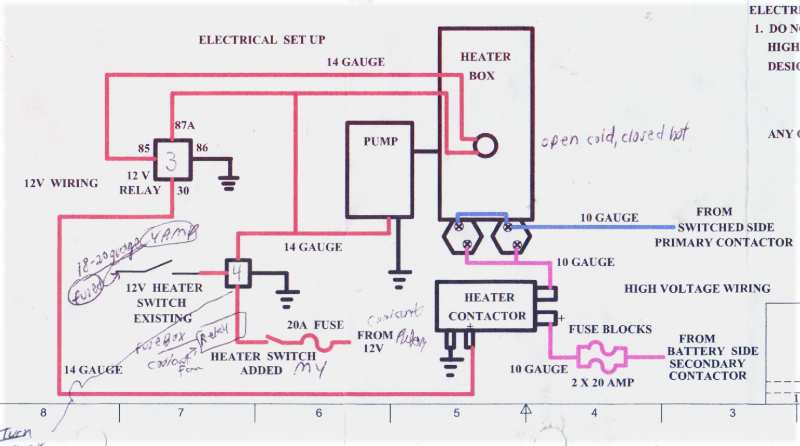
Electric Liquid Heater Schematic Diagram.
The heater box 2 2000 watt elements run off the Saturn’s high 144 voltage system. This current comes by a heater contactor and 2 20 amp KLK fuses located earlier in Electrical box #1.
This contactor I mounted in a new electrical plastic box in front of the heater box behind the bumper.
All the other components like the pump, heater box thermostat, 2 relays, switch in dash, etc are all lower 12 volt driven.
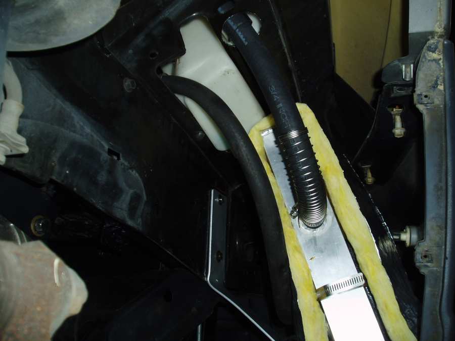
Heater Box With Insulation Started
Two signals need to be given off the original wiring. One is the blower must be on and the other is an added toggle heater switch. If either switch is off the heating elements are not turned on. If the blower is on but the added toggle switch is chosen off the pump will run but the heating elements will not.
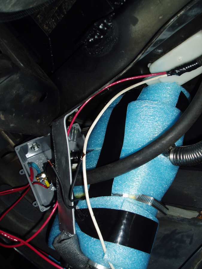
Heater Box With Insulation Done
The heater box is vented into a reservoir which is 1/3rd full. Note there is no pressure on this system.
This heater box will put out a lot of heat and quick. If the system was pressurized there might be lots of trouble keeping the pressure low and not losing coolant. Any expansion or contraction will push or pull water from the reservoir.
Back to the electrical part: On the feed to the positive side of relay #4 coil I made the toggle switch ground the old coolant fan relay in the underhood fuse box(wasn’t using that fuse now that I have no radiator and cooling fan). I now let that relay, through the light blue wire that used to go to the radiator fan, turn on the relay #4.
After getting all systems going I turned on the heater and blower on high. Good volume but no heat. The heater box was hot but the hoses and heater core were cold. I over the next few days tried several things. Installing flush tees to bleed out air on both hoses mounting the tees at the highest points. Tried moving the pump to the lowest point. Tested the pump by placing it in a 5 gallon bucket half full of water. It pumped very well if the impeller was submerged.
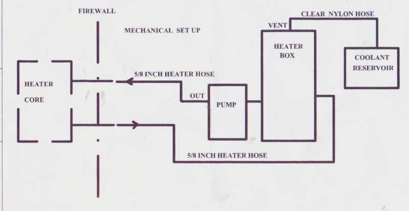
Electric Liquid Heater System Diagram
Lastly it was repaired by flowing the liquid towards the heater core instead of pulling from the core,
as the instruction diagram shows. That is, pulling from the hot box and pushing into the heater core. I guess the core has the normal restrictions where the pump could not overcome. Most centrifugal pumps have lots of push power and almost no pulling power as in an in the tank fuel pump. I thought it did not matter which way the pump moved the liquid, but please follow the instructions next time!?
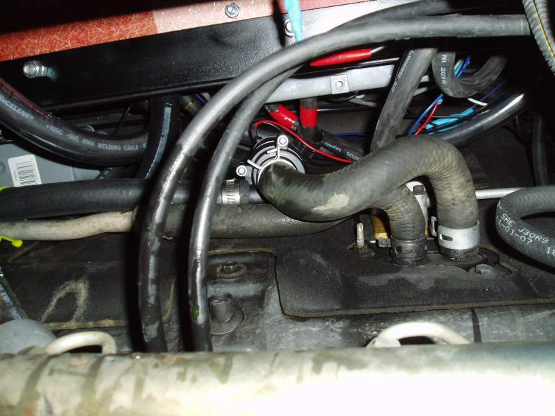
Heater Pump bottom view, when I had it pumping the wrong way

Finished: Right Inner Fender Where the Heater was installed