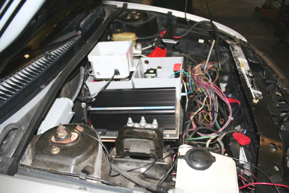
Here I mounted the Curtis Controller on the panel above the cooling fan on top of the heat exchanger with a space for the air to flow.
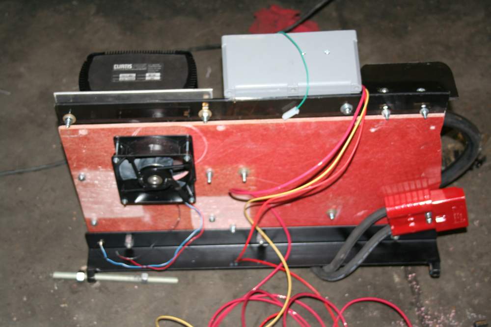
Electrical Panel Bottom View Almost Ready: Here you can see the cooling fan on the left and the Anderson Disconnect on the right. On top is the Curtis Controller on the left, 3 electric boxes in the center and the DC-DC convertor on the right with the plexiglass guard visible.
Electrical Panel Bottom View Almost Ready: Here you can see the cooling fan on the left and the Anderson Disconnect on the right. On top is the Curtis Controller on the left, 3 electric boxes in the center and the DC-DC convertor on the right with the plexiglass guard visible.
Electrical Panel Bottom View Almost Ready: Here you can see the cooling fan on the left and the Anderson Disconnect on the right. On top is the Curtis Controller on the left, 3 electric boxes in the center and the DC-DC convertor on the right with the plexiglass guard visible.

Electric Box #1
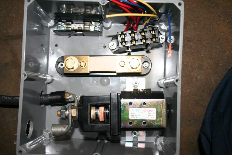
Electric Box #1: This started with me trying to put all 144 volt components in it. At the bottom is the secondary contactor, the ampmeter shunt is in the middle the 4 place fuse panel in the top right and a KLK fuse in the top left.

I was going to wait on adding the heater circuits until later and focus on getting the vehicle through its first test drive but some things are better done now. So I added the 2 KLK fuses for the liquid heater and crimped & shrink all 3 KLK fuse feeds inside the lug on the positive side of the secondary contactor.
Electric Box #2 Final Design
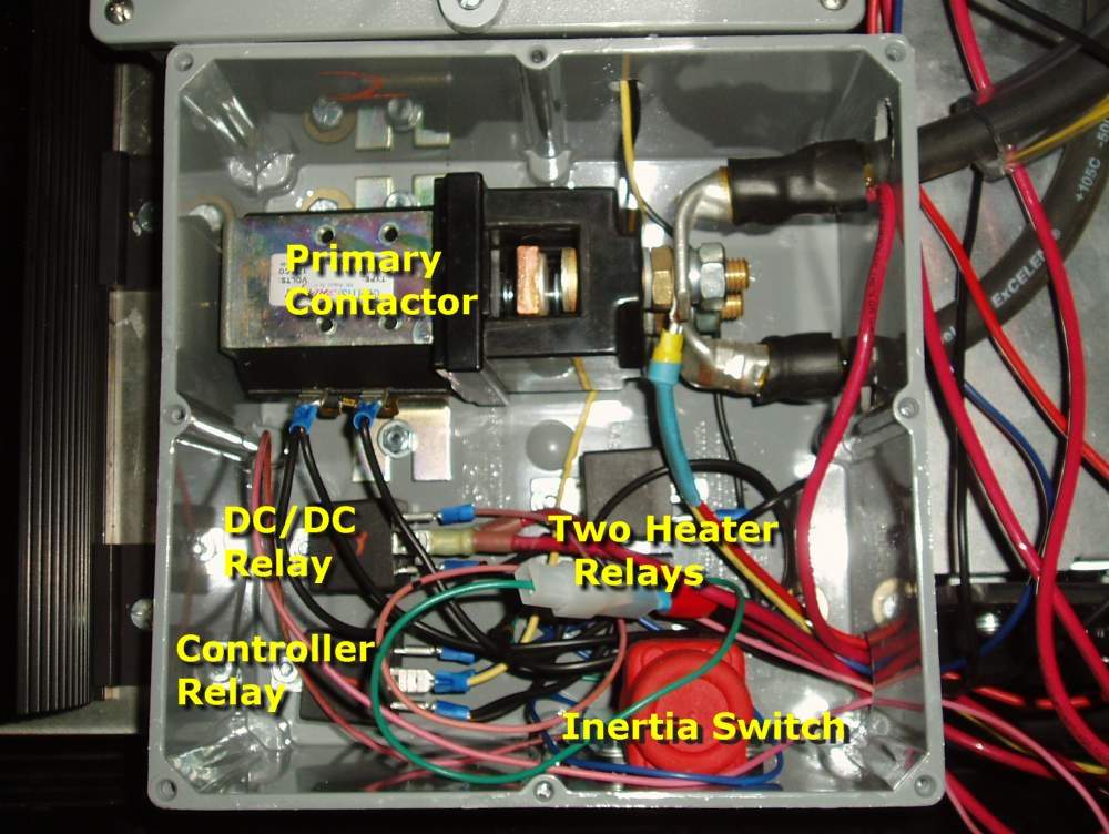
 Electrical Box: I put the potbox in a Electrical Box to protect it from the elements. I noticed some EVers expose their switch but since it has the micro switch and the potentiometer that feed info to the controller and shut off the secondary contactor I wanted the extra protection.